
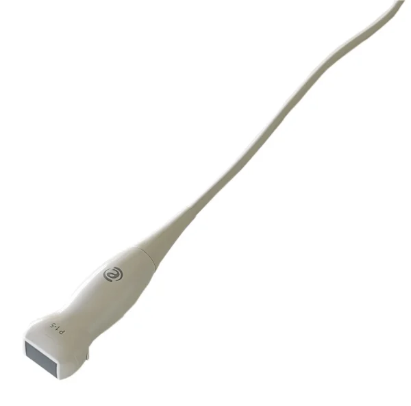
The Esaote P1-5 is a common candidate for repair rather than replacement. This page lists its typical failure modes, self-checks you can run, and the details a repair lab needs from you.
| Manufacturer | Esaote |
|---|---|
| Model | P1-5 |
| Probe type | Phased Array |
| Compatible systems | Esaote MyLab X6 |
The P1-5 typically pairs with Esaote MyLab X6; the same fault can present differently between console revisions, which is why the host system is asked for with the quote details.
Phased arrays like the P1-5 pack tightly spaced elements into a small footprint – edge-element failures distort the sector image early, and cardiac duty cycles accelerate cable fatigue.
Common failure modes for the P1-5
Match what you are seeing against the table below. The right-hand column reflects how faults of this kind typically assess – the actual verdict always depends on the individual probe.
| What you see | Likely cause | Typically repairable? |
|---|---|---|
| Large areas of the array not firing | Widespread element or acoustic stack failure | Usually not economical |
| Fuzzy or noisy image that cleaning does not fix | Lens wear or early element degradation | Case by case |
| Cracked or dented housing | Impact damage; housing can usually be replaced or resealed | Usually repairable |
| Connector lock broken or hardware missing | Broken locking mechanics on the connector housing | Usually repairable |
| Pin damage or corrosion visible in the connector | Connector damage from forced insertion or drops | Usually repairable |
| Image cuts out when the cable is flexed | One or more conductors broken inside the cable bundle | Case by case |
| Cuts, gouges or discoloration on the lens membrane | Mechanical wear or disinfectant damage to the lens | Usually repairable |
| Sector image narrows or loses the apex | Element failure concentrated at the array edge | Case by case |
Check these before you ship the probe
- Run the system’s built-in probe test or element check if your console provides one.
- Check the strain reliefs at both ends for splits, stiffness or separation from the cable.
- Flex the cable gently along its length while imaging – intermittent dropout points to broken conductors.
- Inspect the lens face under good light for cuts, bubbles, lifting edges or discoloration.
- Photograph the complete manufacturer label – the exact revision matters for parts compatibility.
Repair, exchange or replace — which applies to your P1-5
Three paths apply to a failing P1-5: repair (typical for lens, housing, cable and connector damage), exchange (fastest route back to scanning) or replacement (when the acoustic stack is too far gone). The deciding factors are how much of the array still fires, whether the housing is intact and what downtime costs you. Each probe is judged on its actual condition.
What we need to quote your P1-5 repair
- A clear photo of the complete manufacturer and model label on the probe
- A description of the fault: what you see on screen and when it started
- The ultrasound system (console) the probe is used with
- Screenshots or photos of the image problem, if the fault is visual
- Photos of any physical damage – lens, housing, cable or connector
Product imagery on this page is representative of the P1-5 probe family and is not a photograph of your specific unit. This page does not claim OEM authorization or universal compatibility. Repair feasibility, turnaround and commercial terms are confirmed in writing after assessment of the actual probe.


