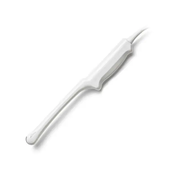
The Mindray P4-2e is a common candidate for repair rather than replacement. This page lists its typical failure modes, self-checks you can run, and the details a repair lab needs from you.
| Manufacturer | Mindray |
|---|---|
| Model | P4-2e |
| Probe type | Phased Array |
| Compatible systems | DC-70, DC-8 |
In service the P4-2e is most often found on DC-70, DC-8. Console-side settings and module revisions still vary, so the exact system build is part of any assessment.
Phased arrays like the P4-2e pack tightly spaced elements into a small footprint – edge-element failures distort the sector image early, and cardiac duty cycles accelerate cable fatigue.
Common failure modes for the P4-2e
Match what you are seeing against the table below. The right-hand column reflects how faults of this kind typically assess – the actual verdict always depends on the individual probe.
| What you see | Likely cause | Typically repairable? |
|---|---|---|
| Bent, broken or corroded connector pins | Connector damage from forced insertion or drops | Usually repairable |
| Outer cable sheath showing cracks, kinks or staining | Jacket wear; conductors may still be intact underneath | Usually repairable |
| Large areas of the array not firing | Extensive element loss across the acoustic stack | Usually not economical |
| Strain relief pulling away from the cable or gone rigid | Flex fatigue where the cable meets the probe or connector | Usually repairable |
| Grainy, low-detail image even after presets are checked | A worn lens surface or elements beginning to degrade | Case by case |
| Image cuts out when the cable is flexed | One or more conductors broken inside the cable bundle | Case by case |
| Connector lock broken or hardware missing | Broken locking mechanics on the connector housing | Usually repairable |
| Sector image narrows or loses the apex | Element failure concentrated at the array edge | Case by case |
Check these before you ship the probe
- Flex the cable gently along its length while imaging – intermittent dropout points to broken conductors.
- Compare penetration and uniformity against a known-good probe on the same preset.
- Inspect the lens face under good light for cuts, bubbles, lifting edges or discoloration.
- Run the system’s built-in probe test or element check if your console provides one.
- Photograph the complete manufacturer label – the exact revision matters for parts compatibility.
Repair, exchange or replace — which applies to your P4-2e
Whether a P4-2e is worth repairing depends on the damage scope: localized lens, cable, strain relief and connector faults are routine repairs, while widespread element loss usually is not economical. An exchange unit can bridge the gap when downtime matters, and replacement becomes rational when repair cost approaches replacement value. A written assessment settles this per probe – condition, not model, decides it.
What we need to quote your P4-2e repair
- A clear photo of the complete manufacturer and model label on the probe
- A description of the fault: what you see on screen and when it started
- The ultrasound system (console) the probe is used with
- Screenshots or photos of the image problem, if the fault is visual
- Photos of any physical damage – lens, housing, cable or connector
Images shown are representative and are not photographs of an individual unit. Nothing on this page claims OEM authorization or guarantees universal fit. Whether a specific P4-2e can be repaired, and on what terms, is confirmed in writing once the probe has been assessed.